
Page 28 - Building Regulation and Design Guidelines - Structural (Grey Code)
P. 28
SECTION: 1 GEOTECHNICAL GUIDELINES & REGULATIONS SECTION: 1 GEOTECHNICAL GUIDELINES & REGULATIONS
strength and the earth pressure is always in terms of effective stresses. (BS
8002: 1994, Section 3.2.3) 63mm HDPE
ANCHOR HOLE
n) Concrete and reinforcement should conform to the requirements of BS GROUT
8004, BS 8110-1 or BS 5400-4, BS 5400-7 and BS 5400-8. The mix should 0.6” ANCHOR STRAND
be designed to provide the necessary structural strength and the flow 2. GROUT HOSE
requirements to ensure adequate compaction and continuity. Special 1. GROUT HOSE
methods of placement, for example by tremie tube should be taken into
account. (Silwinski Z. and Fleming W.G.K, 1974.)
o) Where props or anchors are used, wailing beams should be provided along AA - Cross Section
the face of the wall at this lateral support level to unify shoring behaviour. (unscaled)
The wailing beam may be designed as horizontally spanned steel beams.
The gaps occurred in between the individual piles and the wailing beams ANCHOR HOLE
due to irregularities or deviations from true verticality and position of
individual piles should be wedged or in filled. 1. GROUT HOSE
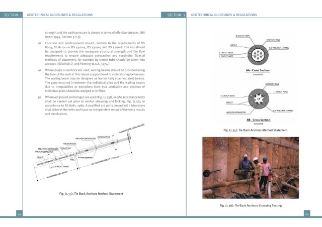
p) Wherever ground anchorages are used (Fig. (1.35)), in-situ acceptance tests 2. GROUT HOSE
shall be carried out prior to anchor stressing and locking, Fig. (1.36), in GROUT
accordance to BS 8081: 1989. A qualified 3rd party consultant / laboratory
shall witness the tests and issue an independent report of the tests results 0.6” ANCHOR STRAND
and conclusions. ANCHOR SEPARATOR
BB - Cross Section
(unscaled)
ANCHOR PLATE, HEAD, WEDGES Fig. (1.35): Tie Back Anchors Method Statement
2nd grout hose A
ANCHOR CENTRALIZER
ANCHOR HOLE
ANCHOR CENTRALIZER 1st grout hose A
ANCHOR SEPARATOR
GROUT B Anchor seperator (change)
ANCHOR FREE LENGHT
SEAL
0.6 INCH STRAND
B
ANCHOR BOUND LENGHT
Fig. (1.35): Tie Back Anchors Method Statement
Fig. (1.36): Tie Back Anchors Stressing Testing
54 55