
Page 24 - Building Regulation and Design Guidelines - Structural (Grey Code)
P. 24
SECTION: 1 GEOTECHNICAL GUIDELINES & REGULATIONS SECTION: 1 GEOTECHNICAL GUIDELINES & REGULATIONS
1.4.1.h Jet-Grout The parameters to be used will be designed and checked with
trial columns prior to start of the works. With jet grouting, it
Jet-grout is the form of jet-grout column “soil-crete pile” by is possible to treat a broad range of grounds, consisting of
drilling a hole specified with its length in the relevant design different type clays, loose sands and to overcome the drawbacks
and then by jetting with proper mixing and pumping equipment of the other injection systems. It is a valid alternative to other
with the jetting parameters to achieve designed diameter.
consolidation systems such as dewatering, micro-piles, stone
Using a drilling rig holes between 400 to 700 mm diameters columns etc.
will be drilled down to required column depth. The drilling
can be carried out by traditional rotary or rotary percussive 1.4.2 SAFETY AGAINST LIQUEFACTION
methods. And then jetting will be done while dragging the drill The hydraulic fill, loose, fine and saturated sands may subject to
set at a specified drag and revolution speed.
liquefaction (significant loss of strength due to buildup pore water
The rig must be equipped with automatically adjustable drag pressure and subsequent deformation in some locations under the cyclic
and revolution speed controls. The jetting takes place at the loading of earthquakes).
bottom of the drilling set at the special tool named “monitor”
with one or two nozzles the diameter of which is from 1.5 mm To mitigate liquefaction hazards, soil improvement is required and its
efficiency shall be ensured from CPT readings pre and post-tests, (ASTM D
to 3.0 mm depending on the design parameters. The cement- 5778 or BS 1377: Part 9: Test 3.1 Amd 8264-95 and SSMFE test Procedure
water mix ejects from these nozzles at minimum pressure of for Cone Penetration Test (IRTP) - 1989 and updated 1997). The pre CPT
300 bars with 250 m/s jet speed.
shall be carried out every 900 m2 maximum or as per project specs and
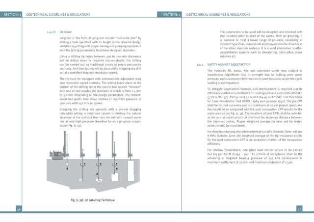
Dragging the drilling set upwards with a pre-set dragging the results to be compared with the post compaction CPT results for the
rate while jetting is continued causes to destroy the natural same area as per Fig. (1.31). The locations of post CPTs shall be selected
structure of the soil and then mix the soil with cement-water at the central points and/or at one third the maximum distance between
mix at very high pressure therefore forms a jet-grout column the improved points. Proper weighted average for near and far tested
as per Fig. (1.31). points should be considered.
For deep foundations, the achievement of 6.0 MPa (Seismic Zone: 2A) and
8 MPa (Seismic Zone 2B) weighted average of the tip resistance profile
for the post compaction CPT is an accepted criterion of the compaction
efficiency.
For shallow foundations, one plate load test/structure to be carried
out (as per ASTM D1194 – 94). The criteria of acceptance shall be the
achieving of targeted bearing pressure of 150 kPa corresponds to
maximum settlement of 25 mm and maximum distortion of 1:500.
Fig. (1.31): Jet Grouting Technique
46 47