
Page 58 - Building Regulation and Design Guidelines - Structural (Grey Code)
P. 58
SECTION: 4 STRUCTURAL DESIGN GUIDELINES - STEEL STRUCTURES SECTION: 4 STRUCTURAL DESIGN GUIDELINES - STEEL STRUCTURES
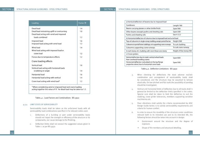
Loading Factor, f
Cantilevers Length/180
Dead load 1.4 Span/360
Dead load restraining uplift or overturning 1.0 Other beams (except) purlins and sheeting rails Span/200
Dead load acting with wind and imposed Purlins and sheeting rails See 4.12.2
loads combined 1.2
Imposed load 1.6 Tops of coloumns in single-storey building, except portal frames Height/300
Imposed load acting with wind load 1.2 Coloumns in portal frame buildings, not supporting crane runways To suit cladding
Wind load 1.4 Coloumns supporting crane runways To suit crane runway
Wind load acting with imposed load or In each storey of a builidng with more thean one storey Height of that storey/300
crane load 1.2 c) Crane girders
1.2 Span/600
from overhead travelling cranes
Span/500
Vertical load 1.6 properties alone) due to horizontal crane loads
Vertical load acting with horizonal loads Table 4.2. Deflection Limitations - BS 5950
(crabbing or surge) 1.4
Horizontal load 1.6 3. When checking for deflections the most adverse realistic
Horizontal load acting with vertical 1.4 combination and arrangement of serviceability loads shall
be considered, and the structure may be assumed to behave
Crane load acting with wind load* 1.2
elastically. On low pitched and flat roofs the possibility of ponding
should be investigated.
* When considering wind or imposed load and crane loading
f
acting together the value of for dead load may be taken as 1.2. 4. Vertical and horizontal limits of deflection due to all loads shall in
general be limited to the deflection limits specified in the codes.
Special care shall be taken to limit the deflection to suit the
cladding, crane girder tolerances, members supporting sensitive
Table 4.1. Load Factors and Combinations - BS 5950
machineries etc.
5. Floor vibrations shall satisfy the criteria recommended by AISC
4.3.4 LIMIT STATE OF SERVICEABILITY
Design Guide Series 11 to satisfy serviceability requirements and
Serviceability loads shall be taken as the unfactored loads with all criteria for human comfort.
serviceability load combinations specified in the relevant codes used.
6. In order to ensure the durability of the structure under conditions
1. Deflections of a building or part under serviceability loads relevant both to its intended use and to its intended life, the
should not impair the strength or efficiency of the structure or its following factors should be taken into account in design:
components, nor cause damage to the finishing.
• Environment around the structure and the degree of
2. Deflection limits shall not exceed the suggested values given in exposure.
Table 2. as per BS 5950.
• Shape of the members and structural detailing.
114 115