Page 60 - Building Regulation and Design Guidelines - Structural (Grey Code)
P. 60

SECTION: 4  STRUCTURAL DESIGN GUIDELINES - STEEL STRUCTURES                           SECTION: 4  STRUCTURAL DESIGN GUIDELINES - STEEL STRUCTURES


                                                                    All beams designed                          1.   Design calculations and details of all parts (See Figure (4.3)) of a
                                                                    to act as ties
                                                                                                                    steel industrial building including foundations shall be submitted.
                                                                       Tie anchoring
                                                                       column A                                 2.   Footings shall be designed to solely resist the horizontal thrust from
                                                                                                                    the portal frames. Hair pin bars connecting pedestal to the grade
                                                                                                                    slab for horizontal restraint shall be avoided.
                                                                                                                3.   A minimum footing effective depth of 300mm for all footings with
                                                                           A
                                                                                                                    reinforcement cover meeting the durability requirements and the
                                                                                                                    recommendations in the soil investigation report shall be provided.
                                                                                                                4.   Connections and loading drawings shall be provided with the input
                              Fig (4.2) Tying of Columns – All beams including secondary beams                      and output from the applicable steel design software.
                                                 used as Ties
                                                                                                                5.   All steelwork drawings shall be properly coordinated with the
                          4.   All horizontal ties, and all other horizontal members, should be                     architectural and services drawings. Bracings shall not foul with
                              capable of resisting a factored tensile load, which should not be                     openings & windows. A minimum of two bays shall be braced.
                              considered as additive to other loads, of not less than 75 kN.
                                                                                                                6.   For built up sections, thickness of structural steel members shall
                          5.   Each portion of a building between expansion joints shall be                         not be less than 6mm for main members and 4mm for secondary
                              treated as a separate building.                                                       members.
                          6.   For special buildings where it is stipulated to be designed to avoid             7.   Anti-sag rods shall be a minimum of 16mm diameter and the
                              disproportionate collapse, all requirements with regard to tying of                   maximum spacing of rods shall not exceed 3.8m. The roof bracing
                              columns,  continuity  of columns,  resistance  to horizontal  forces,                 rods used shall be of 20mm minimum diameter.
                              notional removal of column, accidental loading and key element
                              design etc. shall be carefully studied and designed as required by                8.   Wall wind bracing members shall be rolled steel sections such
                              the relevant sections of codes.                                                       as angles or pipes. Rods or cables shall not be used as wall wind
                                                                                                                    bracing elements.
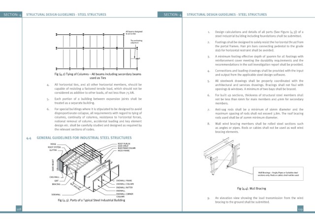
               4.4   GENERAL GUIDELINES FOR INDUSTRIAL STEEL STRUCTURES
                            RIDGE                               ROOF PURLIN
                           ROOF SYSTEM                          EAVE STRUT
                                                                RIGID FRAME COLUMN
                           GUTTER                               RIGID FRAME
                              EAVE HEIGHT            CLEAR SPAN


                                                                                                                                           Wall Bracings – Angle, Pipes or Suitable steel
                                                                                                                                           sections only. Rods or cables shall not be used
                           CMU WALL
                              GIRT                             ENDWALL FRAME
                             BRACING                           ENDWALL COLUMN
                                                               ENDWALL RAFTER                                                   Fig (4.4). Wall Bracing
                                      BAY SPACING
                                                               ENDWALL
                             SIDEWALL                          ENDWALL CORNER
                                                               COLUMN                                           9.   An  elevation  view  showing  the  load  transmission  from  the  wind
                                Fig (4.3). Parts of a Typical Steel Industrial Building
                                                                                                                    bracing to the ground shall be submitted.
          118                                                                                                                                                   119
   55   56   57   58   59   60   61   62   63   64   65