
Page 59 - Building Regulation and Design Guidelines - Structural (Grey Code)
P. 59
SECTION: 4 STRUCTURAL DESIGN GUIDELINES - STEEL STRUCTURES SECTION: 4 STRUCTURAL DESIGN GUIDELINES - STEEL STRUCTURES
• Protective measures. 3. Structural members that support heavy vibrating machinery or
plant should be checked for fatigue resistance.
• Whether inspection and maintenance are possible.
4. Where aerodynamic instability can occur, account should be taken
• As an alternative to the use of protective coatings, weather
resistant steels to BS EN 10155 may be used. Steels of wind induced oscillations.
complying with other prominent international codes such as 5. Where fatigue is critical, all design details should be precisely
the American and European codes are acceptable subject to defined and the required quality of workmanship should be clearly
review and approval by the authority. specified.
4.3.5 FOUNDATION 6. Resistance to fatigue should be determined by reference to BS
7608 or applicable codes.
Foundations shall accommodate all forces imposed on them. Attention
should be given to the method of connecting the steel superstructure to 4.3.8 STRUCTURAL INTEGRITY
the foundations and to the anchoring of holding-down bolts.
All buildings shall be effectively tied together at each principal floor level.
1. Where it is necessary to quote the foundation reactions, it should
be clearly stated whether the forces and moments result are from 1. Each column shall be effectively held in position by means of
factored or unfactored loads. Where they result from factoed loads, horizontal ties in two directions, approximately at right angles, at
each principal floor level supported by that column.
the relevant factors for each load in each combination should be
stated. 2. Horizontal ties shall be provided at roof level, except where the
steelwork only supports cladding that weighs not more than 0.7
4.3.6 HOLDING DOWN BOLTS kN/m2 and that carries only imposed roof loads and wind loads.
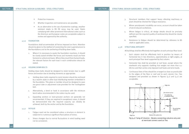
Holding down bolts should be designed to resist tension due to uplift 3. Continuous lines of ties should be arranged as close as practicable
forces and tension due to bending moments as appropriate. to the edges of the floor or roof and to each column line. Ties
1. Holding-down bolts required to resist tension should be anchored designed and provided as shown in Figures (4.1) and (4.2) are
by a washer plate or other load distributing member embedded in acceptable.
the foundation. This plate or member should be designed to span
any grout tube or adjustment tube provided for the holdingdown Column ties Edge ties
bolt.
2. Alternatively, a bend or hook in accordance with the minimum
bend radius recommended in the codes may be used. Re-entrant corner
Tie anchoring
3. Expanding anchors or resin-grouted anchors are generally not re-entrant corner
recommended. If they are required in exceptional cases, it should Edge ties
be demonstrated that the required capacity can reliably be
achieved, both by the anchor and by the foundation.
A
4.3.7 FATIGUE Tie anchoring
column A
1. Fatigue need not be considered unless a structure or element is
subjected to numerous significant fluctuations of stress. Edge ties Beams not used as ties
2. Stress changes due to normal fluctuations in wind loading need Fig (4.1) Tying of Columns – Beams connecting columns only and
not be considered. at reentrant corners used as Ties
116 117