
Page 45 - Building Regulation and Design Guidelines - Structural (Grey Code)
P. 45
SECTION: 3 GUIDELINES FOR PRE STRESSED CONCRETE WORKS (SLABS) SECTION: 3 GUIDELINES FOR PRE STRESSED CONCRETE WORKS (SLABS)
3. Requirement for the other pre stressed tendons 5. Strands shall not be extended from level to another.
shall be as per Section 6 - Technical Report TR43,
second edition. 6. Tendons shall be avoided to be stopped inside the
slab without support at ends. Support can be drop or
c. Tendons hidden beams, walls or columns.
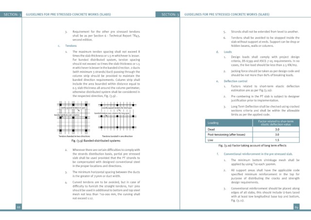
1. The maximum tendon spacing shall not exceed 8 d. Loads
times the slab thickness or 1.5 m whichever is lesser. 1. Design loads shall comply with project design
For banded distributed system, tendon spacing criteria, BS 6399 and ASCE-7-05 requirements. In no
should not exceed 10 times the slab thickness or 1.5 cases, the live load should be less than 2.5 KN/m2.
m whichever is lesser in the banded direction. 2 ducts
(with minimum 3 strands/duct) passing through the 2. Jacking force should be taken as per design code and
column strip should be provided to maintain the should be not more than 80% of breaking loads.
banded direction requirements. Column strip shall e. Deflection control
include the area bounded within distance equal to
0.5 slab thickness all-around the column perimeter; 1. Factors related to short-term elastic deflection
otherwise distributed system shall be considered in estimation are as per Fig.(3.10):
the respected direction, Fig. (3.9) . 2. Pre cambering in the PT slab is subject to designer
justification prior to implementation.
3. Long Term Deflection shall be checked using cracked
evently spaced tendons in span evently spaced tendons for short span
sections criteria and shall be within the allowable
banded tendons over columns for long span
banded tendons over columns limits as per the applied code.
Loading Factor related to shor-term
elastic de ection value
Dead 3.0
Post-tensioning (after losses) 3.0
Tendons banded in two directions Tendons banded in one direction
Fig. (3.9) Banded-distributed systems Live 1.5
Fig. (3.10) Factor taking account of long term effects
2. Wherever there are certain difficulties to comply with
the strands distribution basis, partial pre stressed f. Conventional reinforcement in the pre stressed slab.
slab shall be used provided that the PT strands to
be compensated with designed conventional steel 1. The minimum bottom shrinkage mesh shall be
in the proper locations and directions. applied by using T10 each 300mm.
2. All support areas shall have the applicable code
3. The minimum horizontal spacing between the ducts
is the greater of 75mm or duct width. specified minimum reinforcement in the top for
purpose of distributing the cracks and strength
4. Curved tendons are to be avoided, but in case of design requirements.
difficulty to furnish the straight tendons, hair pins
should be used in additional to bottom and top steel 3. Conventional reinforcement should be placed along
mesh not less than T10-200 mm, the curving shall edges of all slabs; this should include U-bars laced
not exceed 1:12. with at least tow longitudinal base top and bottom,
Fig. (3.11).
88 89