
Page 9 - Building Regulation and Design Guidelines - Structural (Grey Code)
P. 9
SECTION: 1 GEOTECHNICAL GUIDELINES & REGULATIONS SECTION: 1 GEOTECHNICAL GUIDELINES & REGULATIONS
1.2.15 Unconfined Compressive Strength (UCS) MN/m2 (Minimum of Two
Standard Angle of samples for each rock layer especially when pile foundation is used,
Relative Penetration Static Cone Internal enabling the structural designer for calculations of the socket friction
Resistance
State of Density Resistance (q ) Friction and end bearing). Table (1.4) indicates Rock Fracture State, Table (1.5)
Packing (N) c (ø) indicates Rock Strength Classification & Table (1.6) indicates Sandstone/
Tsf or Conglomerate Properties.
Percent Blows / ft Degrees
kgf/cm 2
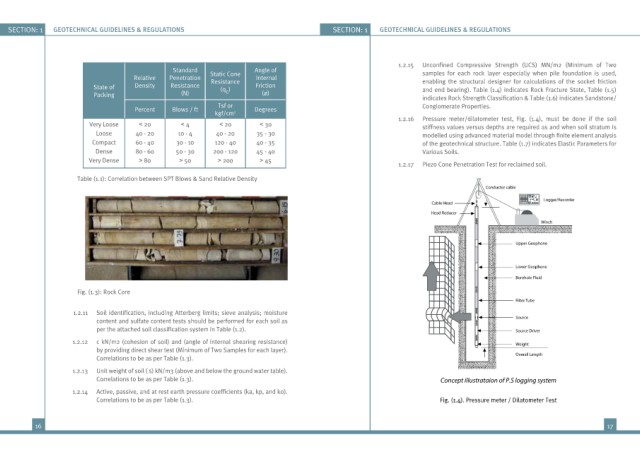
1.2.16 Pressure meter/dilatometer test, Fig. (1.4), must be done if the soil
Very Loose < 20 < 4 < 20 < 30 stiffness values versus depths are required as and when soil stratum is
Loose 40 - 20 10 - 4 40 - 20 35 - 30 modelled using advanced material model through finite element analysis
Compact 60 - 40 30 - 10 120 - 40 40 - 35 of the geotechnical structure. Table (1.7) indicates Elastic Parameters for
Dense 80 - 60 50 - 30 200 - 120 45 - 40 Various Soils.
Very Dense > 80 > 50 > 200 > 45
1.2.17 Piezo Cone Penetration Test for reclaimed soil.
Table (1.1): Correlation between SPT Blows & Sand Relative Density
Conductor cable
Logger/Recorder
Cable Head
Head Reducer
Winch
Upper Geophone
Lower Geophone
Borehole Fluid
Fig. (1.3): Rock Core
Filter Tube
1.2.11 Soil identification, including Atterberg limits; sieve analysis; moisture
content and sulfate content tests should be performed for each soil as Source
per the attached soil classification system in Table (1.2). Source Driver
1.2.12 c kN/m2 (cohesion of soil) and (angle of internal shearing resistance) Weight
by providing direct shear test (Minimum of Two Samples for each layer).
Correlations to be as per Table (1.3). Overall Length
1.2.13 Unit weight of soil ( s) kN/m3 (above and below the ground water table).
Correlations to be as per Table (1.3). Concept illustrataion of P.S logging system
1.2.14 Active, passive, and at rest earth pressure coefficients (ka, kp, and ko).
Correlations to be as per Table (1.3). Fig. (1.4). Pressure meter / Dilatometer Test
16 17