
Page 8 - Building Regulation and Design Guidelines - Structural (Grey Code)
P. 8
SECTION: 1 GEOTECHNICAL GUIDELINES & REGULATIONS SECTION: 1 GEOTECHNICAL GUIDELINES & REGULATIONS
1.2.3 For pad and strip foundations, the depth of soundings or borings below the ground by means of boreholes, simple sampling and testing, making
the anticipated foundation level should normally be between 2.5 and 3 groundwater observations in boreholes, and properly recording the
times the width of the foundation elements (minimum 8.0m depth for information obtained. The boring log shall highlight and describe any
any borehole). Greater depths should usually be investigated in some of fluid loss (mud loss) during drilling at any depth interval, and where ever
the exploration points to assess the settlement conditions and possible open cavities were encountered, (as sudden drop of drilling rods, etc…)
ground water problems subject to the specialist recommendation. For description of the depth interval and field observations shall be included.
rafts, the depth of in-situ tests or borings should normally be equal to Boreholes should be carefully backfilled, concreted or grouted up. Trial
the foundation width. excavations should be outside the proposed foundation areas.
1.2.4 Normally exploration should be undertaken below all deposits that 1.2.9 Geological stratum or design borehole must clarify the thickness of each
maybe unsuitable for foundations purposes, e.g. made ground and weak soil layer with the characteristic properties.
compressible soils, including weak strata overlain by a layer of higher
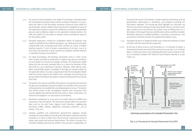
bearing capacity. If rock is found, a penetration of at least 3.00 m in 1.2.10 At the top of Sand stratum, and thereafter at 1 m intervals of depth, a
standard penetration test should be carried out as per Fig. (1.2). For Rock
more than one borehole may be required to establish whether bedrock layers, Continuous rotary core sampling should be used as shown in Fig.
or aboulder has been encountered.
(1.3). Correlation between SPT Blows & Sand Relative Density is as per
1.2.5 For piled foundations, the borings, penetration tests or other in-situ Table (1.1).
tests should normally be performed to explore the ground conditions
to such depth that ensures the design certainty. The exploration depth
below the pile toe level normally taken as 5 times the diameter of the 83.5-kg Drop Standard penetration Test (SPT)
pile shaft or 5.00 m whichever is greater. However, there will be cases Hammer P&D ASTM D 1586
when substantially deeper soundings or borings are needed subject to Repeatedly
Falling 0.78m
the specialist advice. It is also a requirement that the investigation depth AnvII Need to Correct reference
shall be at least equal to the width of the rectangle circumscribing the (ASTM D 4633)
group of piles forming the foundation measured downward from the pile Borehole
toes level. Drill Rod
(”N” or
*A” Type)
1.2.6 The greater the natural variability of the ground, the greater the extent of Split-Barrel Note: Occasional
the ground investigation required to obtain an indication of the character (Drive) Sampler Fourth Increment Used
to provide additional
of the growoints to establish the overall geological structure. The lateral (Thick Hollow soft material
Tube):
and vertical extent of the investigation should cover all ground that O.D. = 50mm
may be significantly affected by the new works or their construction. An I.D. = 35mm
L = 780mm
intensive investigation can only reduce uncertainties. Soothing Q 15m
1.2.7 Boreholes coordinates (x, y) as well as the levels referred to DMD to be First Increment SPT Resistance (N-value)
presented on the site layout. The site layout should reflect the essential Q 15m Hollow sampler Driven in 3 successive increments or “ Blow Counts” is total
data such as the plot limits, legend, north direction, neighbouring N = No. of Blows per 0.3 meters Q 15m Second Increment number of blows to drive
sampler last 300mm
structures, traffic, utilities, vegetation, hazardous chemicals …etc as Third Increment (or blows per feet).
shown in Fig. (1.1).
1.2.8 Suitably qualified and experienced geotechnical engineer should Schematic presentation of an standard Penetration Test
normally be responsible for recording the information obtained from the
borehole as it arises at field; this should include a measured record of
strata, with simple soil and rock descriptions. The driller in charge of an Fig. (1.2): Procedures for Standard Penetration Test (SPT)
individual drilling rig should be skilled in the practice of exploration of
14 15