Page 15 - Building Regulation and Design Guidelines - Structural (Grey Code)
P. 15

SECTION: 1  GEOTECHNICAL GUIDELINES & REGULATIONS                                     SECTION: 1  GEOTECHNICAL GUIDELINES & REGULATIONS


                          safe temporary slope of 35 degrees to the horizontal. Recommendations            1.3.5   DEWATERING:  Care should  be taken during dewatering to ensure
                          for the safe angle for open excavation in different related soil and / or             that fines are not removed during pumping since this could result in
                          rock materials are to be provided, in accordance to related technical                 unpredicted settlements of the surrounding ground and associated
                          guidelines and local requirements.                                                    structures.
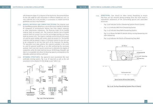
                     1.3.3   BACKFILL MATERIALS AND COMPACTION CRITERIA: The material used                      -   Fig. (1.10) Indicates Surface Dewatering System (French Drains).
                          for backfilling purpose (Maximum 2.00 m thickness) shall be of selected
                          fill  composed  of  sand/granular  mixture  free  from  organic  materials            -   Fig. (1.11) Indicates Well Point Dewatering System
                          or other deteriorates substances. The Plasticity Index of the backfill                -   Fig. (1.12) Indicates Deep Wells Dewatering System.
                          material shall not exceed  10%. The maximum particle size of backfill
                          material shall not exceed 75m and the percentage passing 75m Sieve                    -   Fig. (1.13) Shows the Well Pit Details during running dewatering and
                          shall not exceed 20%. The organic materials content should not exceed                    after dewatering
                          2% and the water soluble salt content shall not exceed 5%. The backfill               -   Fig. (1.14) Indicates the Details of Dewatering Deep Well
                          materials shall be placed in layers of thickness 150mm to 250 mm and
                          to be compacted to not less than 95% of the maximum dry density.
                          The specialist must state whether the material available in site could
                          be used for general backfilling or not after performing the necessary                                        50-100 cm
                          analysis. Sand cone test may be carried out to determine the degree of
                          compaction while the plate load test (as per ASTM D1195/D1195M– 09)
                          also is an acceptable test where the bearing capacity corresponds to the
                          allowable settlement will be confirmed.                                                          m
                                                                                                                           o

                                                                                                                           0                            100-150 mmPVC  Slotted Pipe
                     1.3.4   RETAINING STRUCTURES:  The specialist must recommend the most                                 0  1  -
                          preferable shoring system, Fig. (1.9), (if required) as well as the soil                         0  8                         Geo Textile Wrap
                          parameters to be adopted for the design as per Table (1.3).
                               Step Walls             Concrete         Water
                                                       Seal            above
                                                                      Ground
                                             Complicated
                                               Ground                                                                                  Final Excavation Level

                                                      Deadman
                                                       and
                              Brace                    Raker      Helix
                                                                  and
                              above      Fixed                   Tieback                                                       Typical Section of French Drain System
                             Ground      Length                  Anchor
                                                                                                                       Fig. (1.10): Surface Dewatering System (French Drains)
                                                                        E-80
                                                                       Cooper
                                               ah                External
                                                av                     Railroad
                                                                  Force
                                             Surcharge           on Wall
                                               and       Lagging
                              Limited Embedment  Earthquake  Spacing
                               due to bedrock
                                          Fig. (1.9): Shoring Systems
          28                                                                                                                                                     29
   10   11   12   13   14   15   16   17   18   19   20